
WireLinX™ IoT PLC
Contributed by Buraphatronics, Infineon and BDH Group

WireLinx Programmable Logic Control (PLC) User Manual
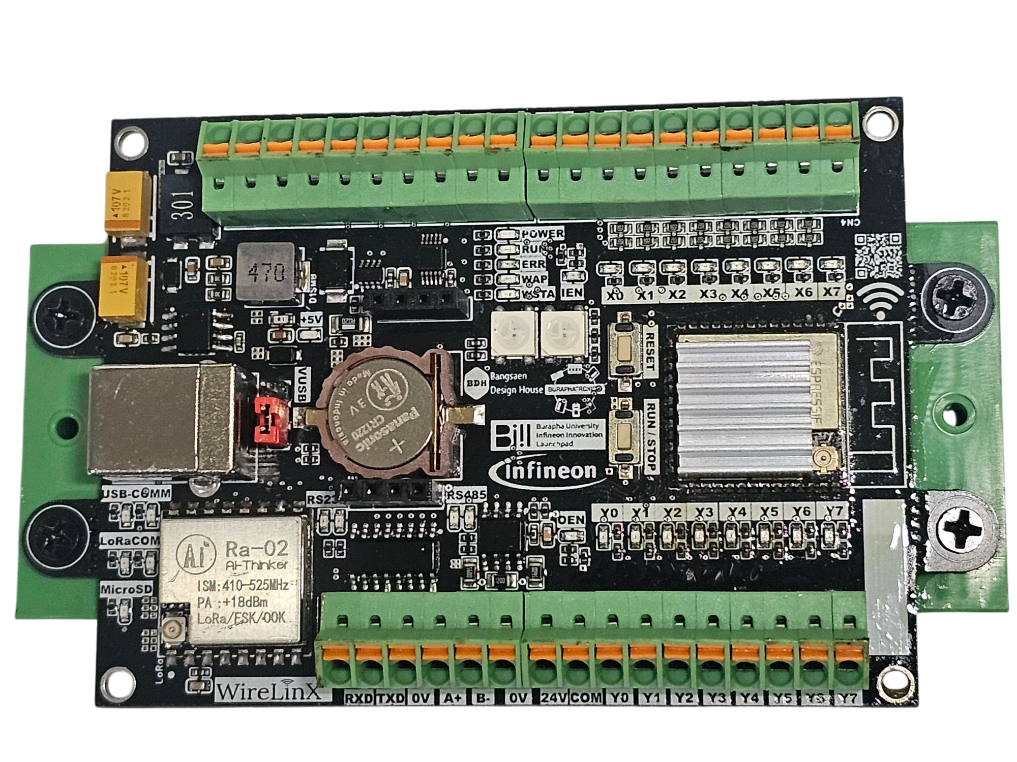
Table of Contents
1. Introduction
Overview of WireLinx PLC
Key Features
Applications
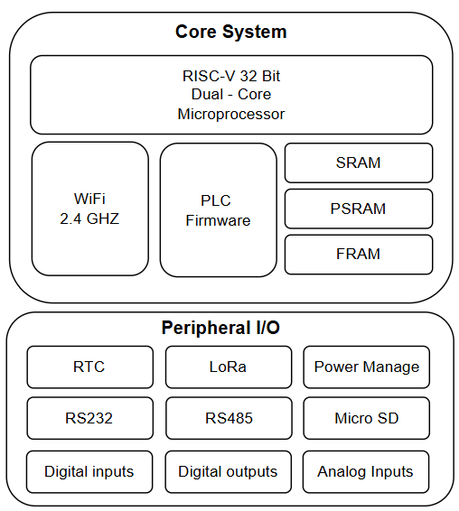
2. Hardware Specifications
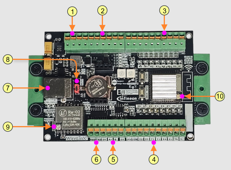
No.
Component
Specification
Number
3. Getting Started
Installing Required Software
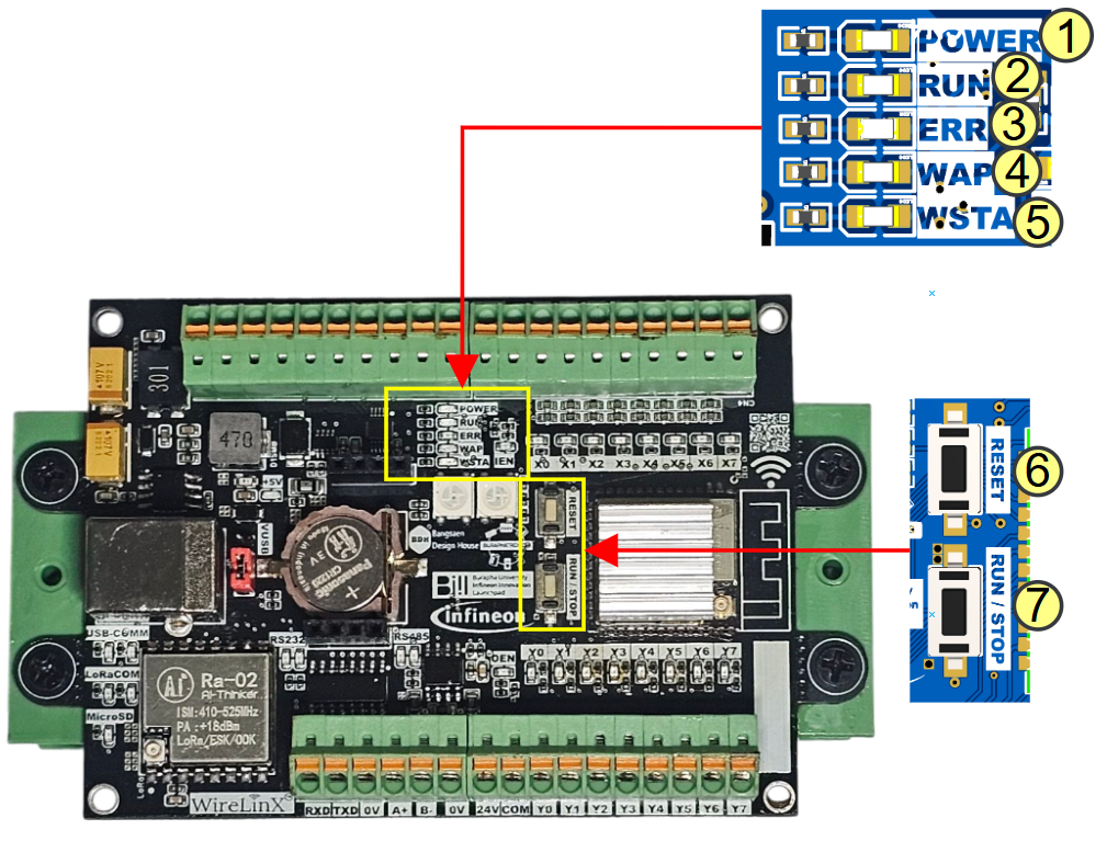
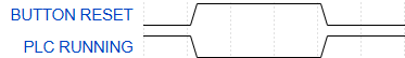
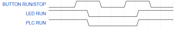
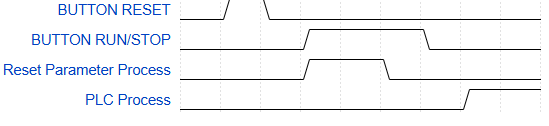
Operating Buttons and Status Indicators
4. Programming WireLinx PLC
Supported Programming Languages
Internal Memory Structure
5. Communication Protocols
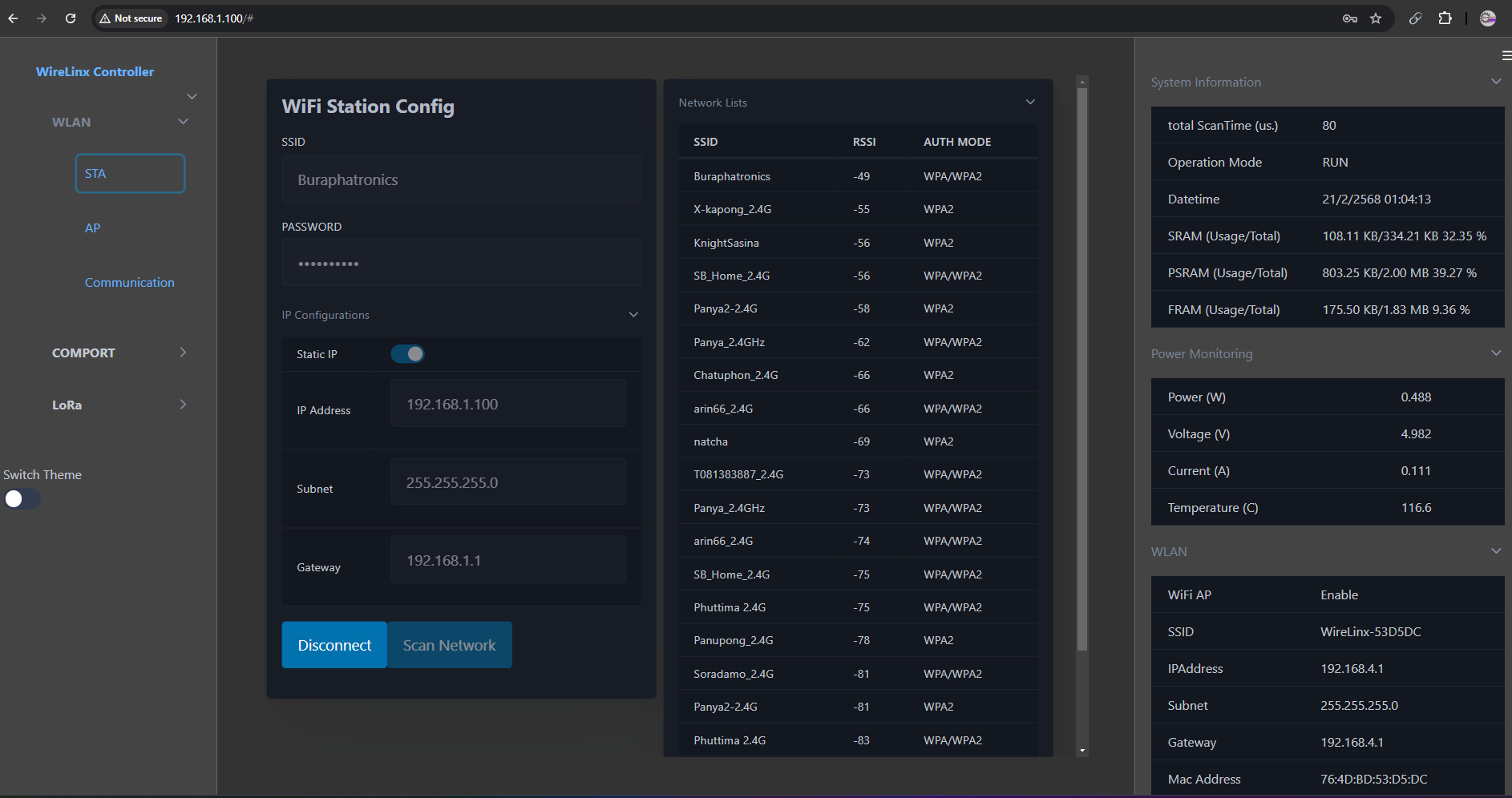
Wi-Fi and Web-based Configuration
RS-232 and RS-485 Communication
Modbus RTU & Modbus TCP
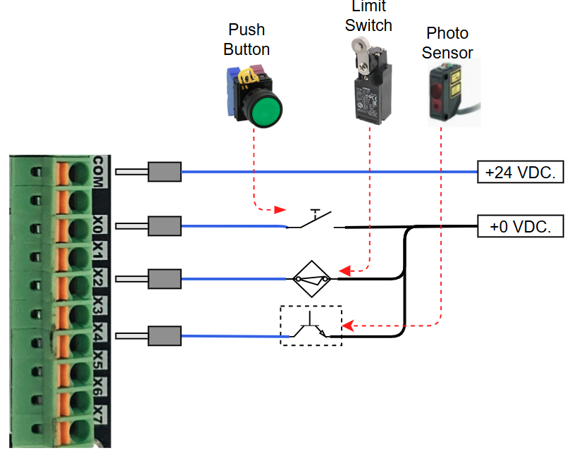
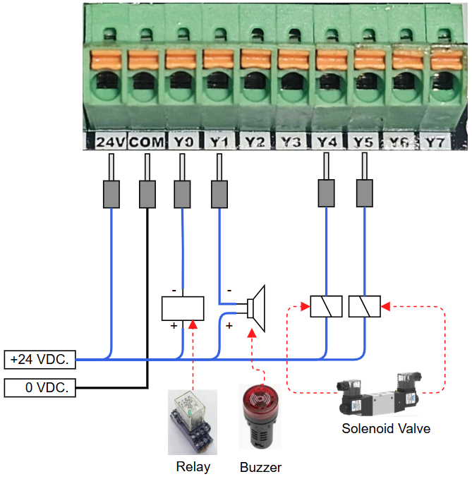
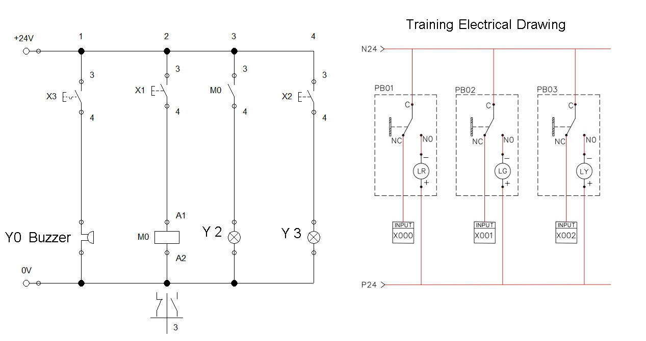
6. Working with I/O
7. Safety and Maintenance
Training Topics for Basic PLC
prepare for trainee
Why need choose PLC.
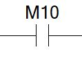
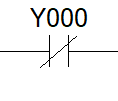
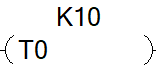
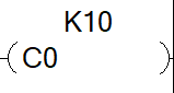
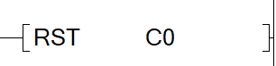
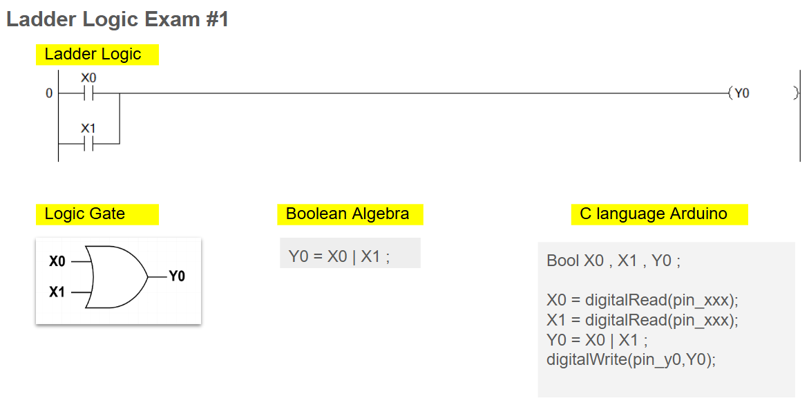
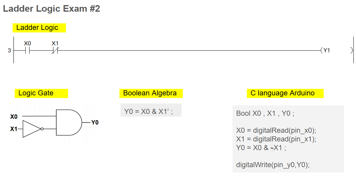
1.Ladder Logic Basics.
No.
Symbol
Description

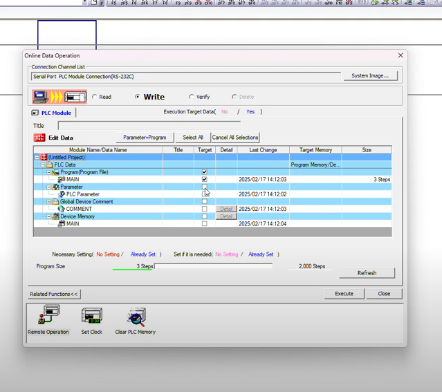
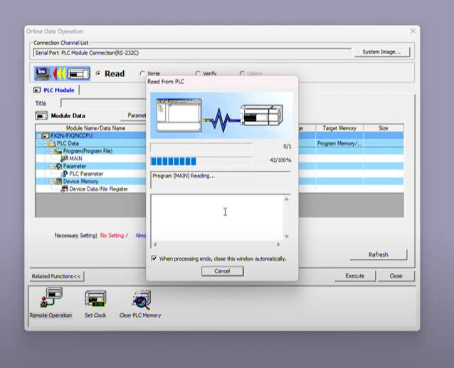
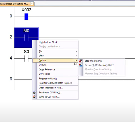
2. Programming with GX-WORK 2.
2.1 new project and test connection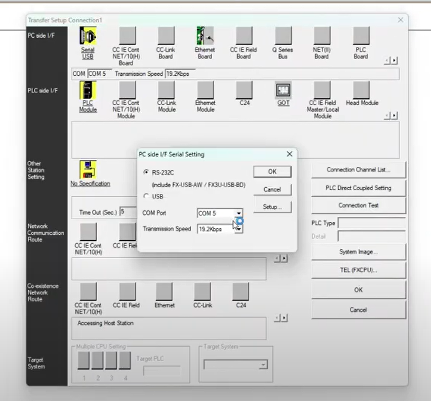
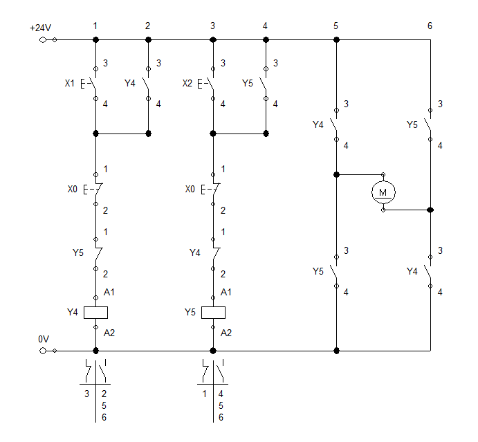
3. PLC Basic Programming Exercises.
Last updated
Was this helpful?